Easy Door Opening
Door opening solution for 2 doors using Facial Biometry without a need for a full fledged access control system.
Main features
- Fast and seamless door opening using Facial Biometry
- No need for large a Access Control Systems
- Scalability - from a small 1 door setups to a large 100s of doors installations
- Mantainning history of accesses
Description
Door opening solution for 2 doors environment with two Smart cameras running the Video Processing Platform Embedded Stream Processor, 2 feedback displays and one relay (with two inputs) using a low power device, such as Raspberry Pi 5 8GB Ram as a server. This package is suitable for both indoor and outdoor installations, however you need to decide for a suitable camera for your environment.
Additional Features
Advanced Access Control Filters
The notifications are filtered by a predefined set of rules and access control strategies. Only the notifications that pass these rules are sent out from the Access Controller.
Feedback Display functionality
Video Processing Platform Station is designed to provide valuable information to both your security staff and the individuals passing through your access points. This includes notifications about successful passages and unsuccessful access attempts. To enhance the user experience, Video Processing Platform Station allows you to display this information directly to the person accessing the point through a feedback display. This feature can be enabled on a mobile device (tablet) positioned near your access points or on any other device capable of running the Chrome browser.
Multiple Watchlists including Blacklists
Unlimited number of watchlists supports your access strategies for different groups of individuals according to their characteristics. You can allow access or restrict access to individuals from set Watchlists, this can be adjusted per door or door group.
You can add multiple images under one enrolled individual to learn different appearances of the individual over time. Ensuring exceptional accuracy even with a face mask on or when an individual’s face attributes gradually change over time.
Flexibility and easy integration with other systems and devices
The Video Processing Platform can be configured according to your needs and allow an easy integration with your devices.
Deployment options
Variety of deployment options are available. It can be used as a single location system, it can be deployed multiple locations using a shared central server or it can be deployed into cloud while still using the advantages of Facial Biometry for Easy Door Opening.
Component Diagram
The component diagram is using harware described in the Hardware requirements section.

Hardware requirements
Video Processing Platform Server
For the Easy Door Opening using the Smart Cameras with the Video Processing Platform Embedded Stream Processor to install Video Processing Platform successfully the Linux hardware must meet the following general requirements:
- x86_64 or ARM CPU
- CPU with support for AVX2 instruction set
- CPU with at least 4 physical cores
- 8GB RAM
- 32 GB of storage
These requirements are meant for an optimized integration package Easy Door Opening using only the SFE Embedded Stream Processor on Smart Cameras. A common out of the box setup has additional requirements.
For this solution you can use a device that is as low powered as the Raspberry Pi 5 with 8GB Ram. Of couse another, more powered device with less drawbacks is also possible.
We will use 1 Video Processing Platform server for this package.
Camera
The Video Processing Platform can use any common RTSP enabled IP camera for the purpose of the access control at the Easy Door Opening. However within the Easy Door Opening packages we are focusing on Smart Cameras that can run the Video Processing Platform Embedded Stream Processor. Depending on your needs we are covering three different camera options. They can be combined freely.
- AXIS M1055-L - indoor camera suitable for 1 entrance
- AXIS M4216-V - indoor camera with varifocal lenses, suitable for more use cases
- AXIS M-2035-LE - indoor/outdoor camera with 2 lenses variations
We will use 2 cameras for this package.
Feedback Display
The feedback display is optional, however greatly improves the user experience. Depending on your environment, using a tablet as a feedback display might not be suitable. Please ensure the tablet is secured and waterproofed/weather proofed as needed.
The Feedback display works by showing a website generated by specifically for a camera, showing the results of the access control in a form of a welcoming message or warning in the case of passage not being allowed. Any tablet/screen that can show a website with animations is suitable, such as Apple iPads or Android devices. It is recommended to run the tablet/screen in the kiosk mode, where random strangers can not manipulate with the visible website.
An example of an Android tablet would be Samsung Galaxy Tab A9+. Even older devices such as the Samsung Galaxy Tab A7 Lite are fully suitable.
We will use 2 Feedback Displays for this package.
Usb C to Ethernet and Power Adapter
It is possible to use the Feedback display with a wifi connection. However this would mean you need to have a WI-FI router within your setup and at the same time you need a good WI-FI coverage coverage for the Feedback Displays. Instead you can use ethernet cables with an USB C to Ethernet and Power adapters. These will connect to the Android/Apple tablets using the USB C connector and at the same time will connect to the Ethernet cable connection and USB C power cable.
There are different models from different brands within various price ranges. An example would be HyperDrive SLIM 8-in-1 USB-C Hub. Ethernet and USB-C power delivery are required.
We will use 2 devices for this package.
POE enabled Switch or POE enabled Wifi router
Power Over Ethernet (POE) enabled 1GBit Switch with suggested 8 ports, while at least 2 ports have POE.
We will use 1 switch for this package.
Relay
We support several network and IOT relays using REST API and MQTT protocols. With our tools new devices can be added easily. If you are using a specific device, please let us know. Within this package we directly support one device - Advantech WISE 4000 series, suitable for up to 4 doors using REST API.
Installation
Once you have the required hardware ready, you can start with installation. We recommend to mark each device, so it is clear what name does each device have and to which node it belongs.
Network Installation
Use the Component Diagram as a guide for how to plug different components into your network. Choose the one matching your relay type. The Edge cameras needs to be plugged into POE (Power over Ethernet) ports on your POE switches.
IP Address Configuration
After the devices are physically connected into the network we can set up the IP addresses for each device. Below is a table of IP addresses used for this package to make it run out of the box. On each device set the manual IP address as below and use the subnet mask: 255.255.255.0 and the default gateway: 192.168.17.1.
| Central Devices | IP Address | Description |
|---|---|---|
| Raspberry Pi | 192.168.17.10 | Central Video Processing Platform Server |
| Advantech WISE 4000 Series | 192.168.17.20 | Network relay |
| Configuration for Door #1 | IP Range | Description |
|---|---|---|
| Camera | 192.168.17.21 | Local Camera used within the 1st door location |
| Feedback Display | 192.168.17.22 | Feedback Display used within the 1st door location |
| Configuration for Door #2 | IP Range | Description |
|---|---|---|
| Camera | 192.168.17.31 | Local Camera used within the 2nd door location |
| Feedback Display | 192.168.17.32 | Feedback Display used within the 2nd door location |
We have more information available about setting up the IP addresses for Nodes and Cameras.
Video Processing Platform Server
We need to install Video Processing Platform the server device. For each node we need a license.
On your Nodes open the Terminal. Navigate to location /srv/ using the command:cd /srv
Then clone the git repositorygit clone https://github.com/innovatrics/smartface.git
Apply License
Each instance of the Video Processing Platform needs a license. For more context and information about how to get and apply the license visit our Get Started documentation. Video guide is available.
Copy the license files into the folder package-easy-door-opening:/srv/smartface/special/package-easy-door-opening
Run the Video Processing Platform
Depending whether this is a local or central node, run the run.sh script located in the folder:
/srv/smartface/special/package-easy-door-opening
For more context and infomation about installing read our Get Started documentation.
Once the installation successfully went through, the Video Processing Platform is running. Visit the installation’s Video Processing Platform Station using your own IP address, or localhost on the URL such as http://localhost:8000/ or http://your-ip-address:8000/. Endure each node is up and running before proceeding.
Camera Installation
For the Easy Door Opening package we will use the Edge Cameras equipped with Embedded Face Recognition, specifically using the Video Processing Platform Embedded Stream Processor. They allows us to keep the server hardware requirements at the minimum, while providing high quality face recognition.
Power
Connect your camera into the POE enabled switch using a common ethernet cable. The recommended switch does have POE enabled.
Camera Network Configuration
Set up the network settings of the camera to match your desired network architecture. Look at sample of network configuration. The default IP address of most AXIS cameras is typically set to 192.168.0.90. However, if no IP address is assigned or it conflicts with other devices, the camera may obtain an address via DHCP if a DHCP server is present on the network.
To locate the camera, AXIS provides a tool called AXIS IP Utility or AXIS Device Manager that can help find and configure the camera’s IP address if needed. If you’re unable to access the camera, it may also be necessary to reset the camera to factory defaults, which will restore the default IP address.
You can change the IP Address manually without using any external tools. You need to connect the powered camera (POE) to a network, so it is reachable by your device, such as laptop, or one of the NUCs. If your network is not DHCP enabled, we suggest to set temporarily your device’s IP Address to be within the same range, such as 192.168.0.150.
Visit the camera’s ip address, using it as URL in your browser 192.168.0.90, where you are prompted for setting up the password. Set new password for the root user as per password quality requirements.
Within the camera web UI, navigate to the System, Network where you can see the IPv4 setup. Use the IPv4, where you can define IP address, Subnet mask and Router (Gateway) to match the IP Address Configuration. Click Save.

After succesfully applying the updated network configuration, you will need to connect to the new IP Address. To do so you will need to update the IP Address of the connected device (NUC/Laptop) to be within the right range. For this sample within the range of 192.168.17.*.
Position
We are aiming at positioning your Edge cameras correctly to avoid common facial biometry challenges. More information about where and how to mount and setup a camera is available here. This includes information about how to set up focus, lighting, colors and zoom.
SFE Stream Processor
An Edge camera is a Smart camera using the Video Processing Platform Embedded (SFE) Stream Processor. The Video Processing Platform Embedded (SFE) Stream Processor is a face recognition pipeline processing camera input and performing real-time face recognition on edge devices, like smart cameras and AI boxes.
We will install the SFE Stream Processor on each Smart Camera. Please follow instructions below how to ensure the camera’s firmware is up to date and how to install the plugin.
Firmware
To successfully install the SFE Stream Processor Plugin for Axis, ensure you have the camera updated to firmware at least with the version: 11.11.73.
Install
Instructions on how to install SFE Stream Processor on supported Axis camera are available here. If you prefer a video guide, it is available below:
Installing SFE Stream Processor on a camera includes obtaining and applying a license for each camera. More information about the process of obtaining and applying licenses is available here.
Connect to MQTT Broker
Once the plugin is installed you can configure it to connect to the Video Processing Platform MQTT Broker. The Video Processing Platform MQTT Broker has the same IP Address as the Video Processing Platform server. Then click the LAUNCH button to start the SFE Stream Processor.
Populating Cameras into the Video Processing Platform
Each installed camera needs to be added into the Video Processing Platform. Please follow the steps to do so.
Feedback Display Installation
Connect the tablet intended to be a feedback display in the ethernet network using the additional USB C to Ethernet and Power adapter. Ensure the tablet has correct network configuration.
Depending on your use case it might be meaningful to put the Feedback Display into some encasing together with the camera, or at least mount the together. The Feedback Display should be visible when approaching the doors.
Within encasing:

Open encasing:

To enable the Feedback Display on each camera, follow the instructions.
Relay Installation
Set up your username, password and set the IP Address, Subnet mask and Gateway as per the IP Address Configuration section.
For physical installation of the Network Relay, especially the wiring, please look at the documentation of the relay.
Configuration
Video Processing Platform Server
Define and set up watchlists
You can define your own Watchlists and enroll your own WatchlistMembers. This can be done using the Video Processing Platform Station available at the port 8000 for each node, the manual is here or via the REST API. For more context, read about Watchlist Management and WatchlistMember Management.
Keep in mind the Watchlists can have their own colors to be easily distinguished and they can have their own biometric Matching Threshold. For a restricted Watchlists, such as “Blacklists” you can set the Watchlist color to be RED.
For the door opening use case you generally want to have the Threshold to be set generally higher to ensure only the correct Watchlist Members would be let in. Depending on size of your Watchlists a good starting value would be 60.
Consider what Watchlists should be able to open the doors as that is something we will setup in Watchlists matching & synchronisation for the cameras.
Choose data retention and saving strategy
To adjust the time for which data is retained, you can do the Data retention configuration for each node. The amount of days for storing data will limit the ability to investigate using the History Event. To avoid issues with using all the space on the server machine it is recommended to set a value. Due to a restricted amount of space available at the Raspberry Pi 5, we would suggest a low value, such as 5 days.
Default setup for the Raspberry Pi setup has saving the data disabled.
Camera Configuration
Added Edge cameras can be configured. Detailed manual is available here. There are several recommended configurations optimized for the Event security. Please consider applying the configuration below:
- Face processing : Enabled
- Face save strategy: Balanced
- Min face size: 20px, Max face size: 300px
- Messaging : Enabled
- Strategy: On new and Interval
- Interval: Optimal (250ms)
- Send crop images : Enabled
- Send full frame images : Disabled
- Watchlists matching & synchronisation: Enabled
- Enable Watchlists you want to be able to open the doors. Set a matching threshold for all the Watchlists.
Liveness configuration
The Liveness Check is a process of determining whether the presented face is a real person, or if the presented face has been faked during some kind of so-called spoof attack. This process is sometimes also called a Spoof Check.
A good starting position holding a good balance between False Accept Rate and the False Reject Rate would be set to 84. More information about passive liveness threholds is available here.
To set the Liveness/Spoof check, set it for each camera as per instructions.
Access Control Configuration
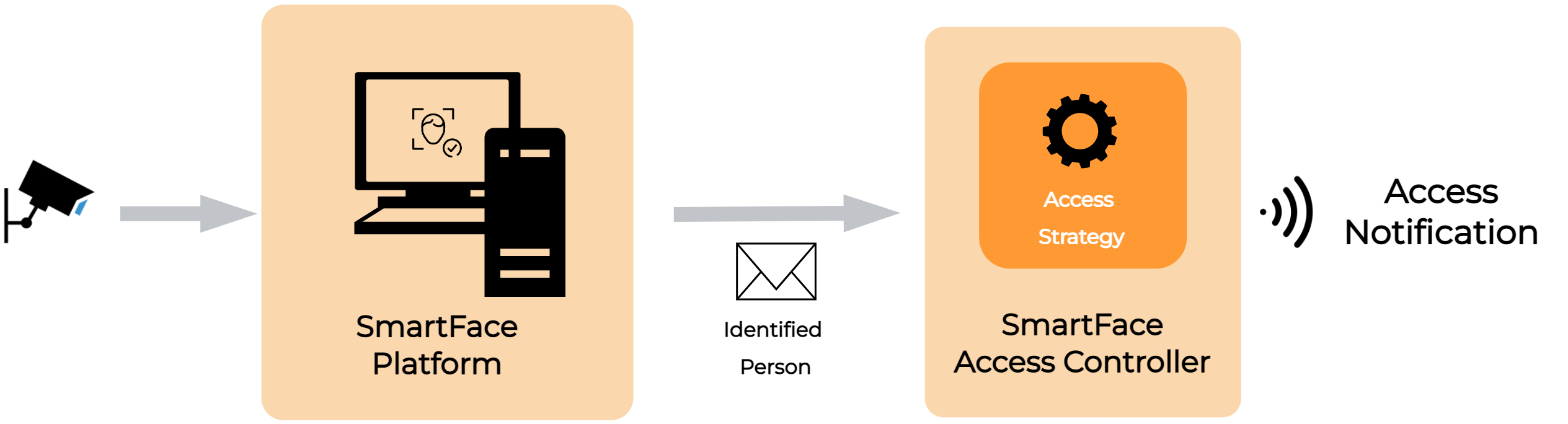
The Video Processing Platform Access Controller is a standalone module that listens to notifications coming from the Video Processing Platform about people matched against watchlists.
The notifications are filtered by a predefined set of rules and access control strategies. Only the notifications that pass these rules are sent out from the Access Controller. This component is used for the access control use case, where seamless and friction-less opening of access points (turnstiles, doors, barriers, ramps, etc.) is required.
The rules cover many common elements of the access control, such as control whether only the closes person to the camera can open the door, whether to use liveness check, how often to send the opening signal to the relay etc.
Manual for setting up the Access Controller are available here. Default (available in the package) and recommended values are:
FilterConfiguration__FaceOrderConfiguration__Enabled=false
FilterConfiguration__FaceOrderConfiguration__Order=1
FilterConfiguration__OpeningDebounceConfiguration__OpeningDebounceEnabled=true
FilterConfiguration__OpeningDebounceConfiguration__OpeningDebounceMs=4000
FilterConfiguration__BlockingDebounceConfiguration__BlockingDebounceEnabled=true
FilterConfiguration__BlockingDebounceConfiguration__BlockingDebounceMs=4000
FilterConfiguration__ExclusiveCameraConfiguration__Enabled=true
FilterConfiguration__ExclusiveCameraConfiguration__ExclusivityMs=5000
FilterConfiguration__NotIdentifiedPersonConfiguration__Enabled=true
FilterConfiguration__NotIdentifiedPersonConfiguration__RoamingLimitTimeMs=3000
FilterConfiguration__FaceMaskConfiguration__Enabled=false
FilterConfiguration__FaceMaskConfiguration__DenyingDebounceMs=4000
FilterConfiguration__IntentionalAccessConfiguration__Enabled=false
FilterConfiguration__SpoofCheckConfiguration__Enabled=true
FilterConfiguration__SpoofCheckConfiguration__DenyingDebounceMs=4000
FilterConfiguration__SpoofCheckConfiguration__SpoofRateLimitingConfiguration__Enabled=true
FilterConfiguration__SpoofCheckConfiguration__SpoofRateLimitingConfiguration__SpoofAttemptsCount=5
FilterConfiguration__SpoofCheckConfiguration__SpoofRateLimitingConfiguration__SpoofAttemptsWindowMs=120000
FilterConfiguration__SpoofCheckConfiguration__SpoofRateLimitingConfiguration__BlockingTimeIncrementCooldownMs=10000
FilterConfiguration__SpoofCheckConfiguration__SpoofRateLimitingConfiguration__BlockingTimeIncrementMs=30000
FilterConfiguration__SpoofCheckConfiguration__SpoofRateLimitingConfiguration__MaxBlockingTimeMs=300000
Access Control Connector Configuration
Part of the package is the Access Control Connector that serves as a connector between the Video Processing Platform and a physical device - the Network Relay.
The Access Control Connector code is available at the Github as you have freedom to update the code to match your advanced setup and add more devices, that are currenly not supported.
To configure the relay edit the .env.actrlcon file within the package directory. Setup each camera:
Each line starts like this, using camera index, starting at 0:
AccessControlMapping__0__
Then comes the actual variable:
StreamId
This is ID of the Edge/Smart Camera. You can get in either using the REST API or in the Video Processing Platform Station, when you go to the Cameras section and click on the camera in the list. The value is the last part of the URL, such as
http://192.168.17.10:8000/cameras/edge-stream-detail/9eababd7-c1c3-45f3-9b51-05b721afd467. In this case the value would be: 9eababd7-c1c3-45f3-9b51-05b721afd467.
Host
This is the IP Address of the Advantech Wise 4000 series device (Relay). In the default setup it is 192.168.17.20.
Port
This is the port for communication with the Relay.
Channel
This is chosen channel. The Relay has 4 channels to choose from, so it can actually control 4 doors. The index starts with 0.
Username
Username used to control the Relay. Can be set in the Relay.
Password
Password used to control the Relay. Can be set in the Relay.
Sample code for 2 cameras:
# Door #1 Camera
AccessControlMapping__0__StreamId=d8c46821-1a2f-4a91-9173-7cf78022cbef
AccessControlMapping__0__Host=192.168.17.20
AccessControlMapping__0__Port=80
AccessControlMapping__0__Channel=0
AccessControlMapping__0__Username=root
AccessControlMapping__0__Password=12345678

# Door #2 Camera
AccessControlMapping__1__StreamId=18648d65-c083-43a4-8b92-5ae1794addb6
AccessControlMapping__1__Host=192.168.17.20
AccessControlMapping__1__Port=80
AccessControlMapping__1__Channel=1
AccessControlMapping__1__Username=root
AccessControlMapping__1__Password=12345678
Apply any changes by using the command docker compose up -d within the package directory.
Relay Configuration
Information about how to setup the relay is available. Choose your mode and delay time based on your door setup.
How to use the seamless Easy Door Opening
When the package is set, up and running you can approach the door and camera, the door is opened and you can seamlessly enter the door as long as you are enrolled into a Watchlist that is synced with the Edge cameras.