Relay Connector
SmartFace provides face biometry for various purposes including the access control and attendance use cases. Communication with various devices is supported over the network. For such devices we provide the Relay Connector module.
Relay Connector
The module connects to SmartFace AccessController gRPC stream, process GRANTED notifications and send Open request to a Relay Connector. You can use existing connectors or write your own so it will send data over the network using the connectors.
Development
With the provided Relay Connector module you can easily add support for your own hardware and software. To add such new HW or SW, you can easily create your own class based on the AdvantechWISE4000Connector.cs file in the Connectors directory.
The source code is available on our Github repository. To run application localy, follow these steps
- clone the
https://github.com/innovatrics/smartface-integrations/Github repository using the git commands or download the code uzing the “Download Zip” button - open terminal
- navigate to
/src/RelayConnector - run
dotnet run
Deployment
To deploy the module, follow these steps:
- open terminal
- navigate to
/src/RelayConnector - for MS Windows version run
run dotnet publish -c Release -r win10-x64 --self-contained true -p:ReadyToRun=false -p:PublishSingleFile=true -p:PublishTrimmed=false -p:IncludeNativeLibrariesForSelfExtract=true -p:IncludeAllContentForSelfExtract=true - for Linux (x64) version run
run dotnet publish -c Release -r linux-x64 --self-contained true -p:ReadyToRun=false -p:PublishSingleFile=true -p:PublishTrimmed=false -p:IncludeNativeLibrariesForSelfExtract=true -p:IncludeAllContentForSelfExtract=true
Deploy to Docker
- navigate to root of this repo
- the following commands are samples and you will likely need to use your own repository to upload your version of the code. If you do not wish to do any changes, you can use the code provided by us as per the usage section of this page. Please adjust the version if needed, instead of 1.3 please use your desired version number. The one provided in the sample commands below is the current version.
- run build for docker and push to a registry, please use the following commands
docker build -f src/RelayConnector/Dockerfile -t registry.gitlab.com/innovatrics/smartface/integrations-relayconnector:1.3 .docker tag registry.gitlab.com/innovatrics/smartface/integrations-relayconnector:1.3 registry.gitlab.com/innovatrics/smartface/integrations-relayconnector:latestdocker push registry.gitlab.com/innovatrics/smartface/integrations-relayconnector:1.3docker push registry.gitlab.com/innovatrics/smartface/integrations-relayconnector:latest
Configuration
When running the application you can configure it via the appsettings.json file in the Windows version, or using the environment variables in the .env.rc file when the module is deployed as a docker container. There are few settings you can adjust for your project.
You can adjust the IP address and the port used by the SmartFace server’s Access Controller module that is being used as a provider of the GRANTED/DENY decisions.
...
 "AccessController": {
        "Schema": "http",
        "Host": "192.168.1.10",
        "Port": 5050
    },

...
You can adjust mappping for each camera. Each camera can be binded to another network relay, so you need to use the camera’s stream ID value (you can get as a id value via the REST API from the endpoint GET /api/v1/Cameras ).
This guide shows you the steps needed to setup a RTSP Camera. The steps needed to setup an Edge Camera as an input to the relay connector is very similar. The main difference is that you use another endpoint to get the StreamId value. In the case of an Edge Camera it is GET/api/v1/EdgeStreams
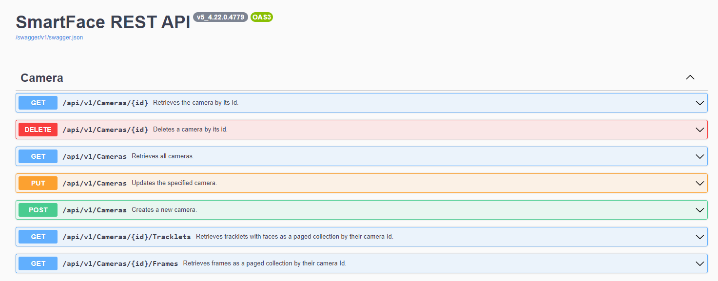
Camera Endpoints
Sample output of such endpoint would be similar as the snippet below. Please keep in mind, this is just a part of the outcome you will receive:
[
  {
    "spoofDetectorResourceIds": [
      "none"
    ],
    "id": "e4e6791c-92b2-4ab2-8086-20bdb8f5302f",
    "name": "Test Camera",
    "source": "rtsp://user:password@192.168.1.200:554/onvif/H.264/media.smp",
    "enabled": true,
    "faceDetectorConfig": {
      "minFaceSize": 35,
      "maxFaceSize": 600,
      "maxFaces": 20,
      "confidenceThreshold": 450
    },
...
Once you have the id value, you can configure information related to the network relay device, such as the Stream ID (please use the camera’s id) it’s IP address, channel used (common relays allow several) and the device’s username and password.
...
    "RelayMappings": [
        {
            "StreamId": "00000000-0000-0000-0000-000000000000",
            "IpAddress": "1.1.1.2",
            "Channel": 0,
            "Username": "user",
            "Password": "password"
        }
    ]
}
...
Usage
Usage
Add following pattern to existing docker compose file (docker-compose.yml) and set up the .env.rc file as described above:
...

  sf-station:
    image: ${REGISTRY}sf-station:${SFS_VERSION}
    container_name: SFStation
    restart: unless-stopped
    ports:
      - 8000:8000
    env_file: .env.sfstation

  relayconnector:
    image: ${REGISTRY}integrations-relayconnector
    container_name: SFRelayConnector
    restart: unless-stopped
    env_file: .env.rc

networks:
  default:
    external:
      name: sf-network
If needed the environment variables normally defined in the .env.rc file can be defined directly in the docker-compose.yml file too:
  ...

  sf-station:
    image: ${REGISTRY}sf-station:${SFS_VERSION}
    container_name: SFStation
    restart: unless-stopped
    ports:
      - 8000:8000
    env_file: .env.sfstation

  relayconnector:
    image: ${REGISTRY}integrations-relayconnector
    container_name: SFRelayConnector
    restart: unless-stopped
    environment:
      - AccessController__Host=SFAccessController
      - AccessController__Port=80
      - RelayMappings__0__StreamId=ec0437ae-7716-4141-99d9-a9b2a4dd2106
      - RelayMappings__0__IpAddress=ip-of-the-relay
      - RelayMappings__0__Channel=3
      - RelayMappings__1__StreamId=d5ff8f40-f900-4492-8ecc-6a2539648964
      - RelayMappings__1__IpAddress=ip-of-the-relay
      - RelayMappings__1__Channel=3

networks:
  default:
    external:
      name: sf-network
Advantech Wise 4000 Relay Connector
One of the possible network relays to be used is the Advantech Wise 4000 Relay Connector.
WISE 4060 LAN – CIRCUIT BOARD, 4-ch DI and 4-ch Relay IoT Ethernet I/O Module
- Advantech WISE-4000 Series
- IEEE 802.3u 10/100Base-T(X)
- Industrial grade operating temperature -40~70°C
- Supported Protocols: Modbus/TCP, TCP/IP, UDP, DHCP, HTTP
- Supports RESTful web API in JSON format
- Supports local logging with RTC time stamp
- Supports mobile device web configuration in HTML5
- Supports 10~30VDC power with reverse protection
Setup IP address
The device has factory settings as follows:
IP: 192.168.1.100
username: root
password: 00000000
To configure the device, please visit http://192.168.1.100/config/index.html from within the same network. To make things easier we would recommend to temporarily set your ip manually to be within the 192.168.1.* range.
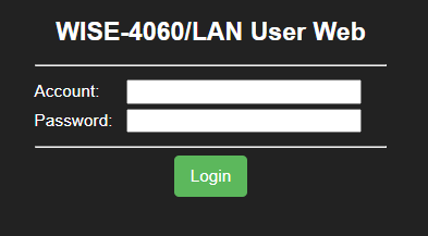
Login Form
Please go to Configuration->Network where you can adjust the IP Address.
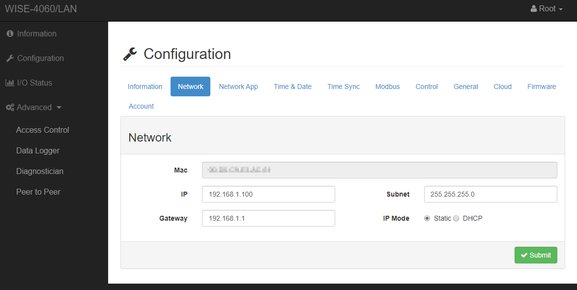
Network Configuration
Setup the Relay
To setup the relay behaviour, please visit I/O Status -> Relay. Here you can see the current channel setup and you can turn each channel on and off.
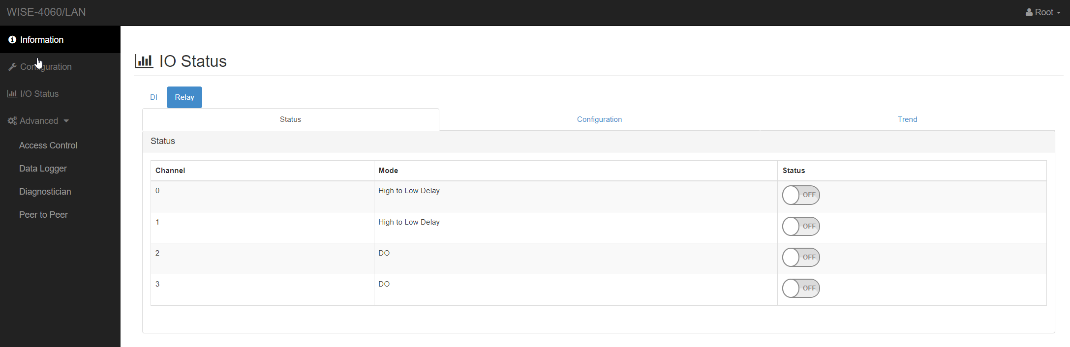
Channel Status
Please click on the Configuration to set up each channel’s behaviour.
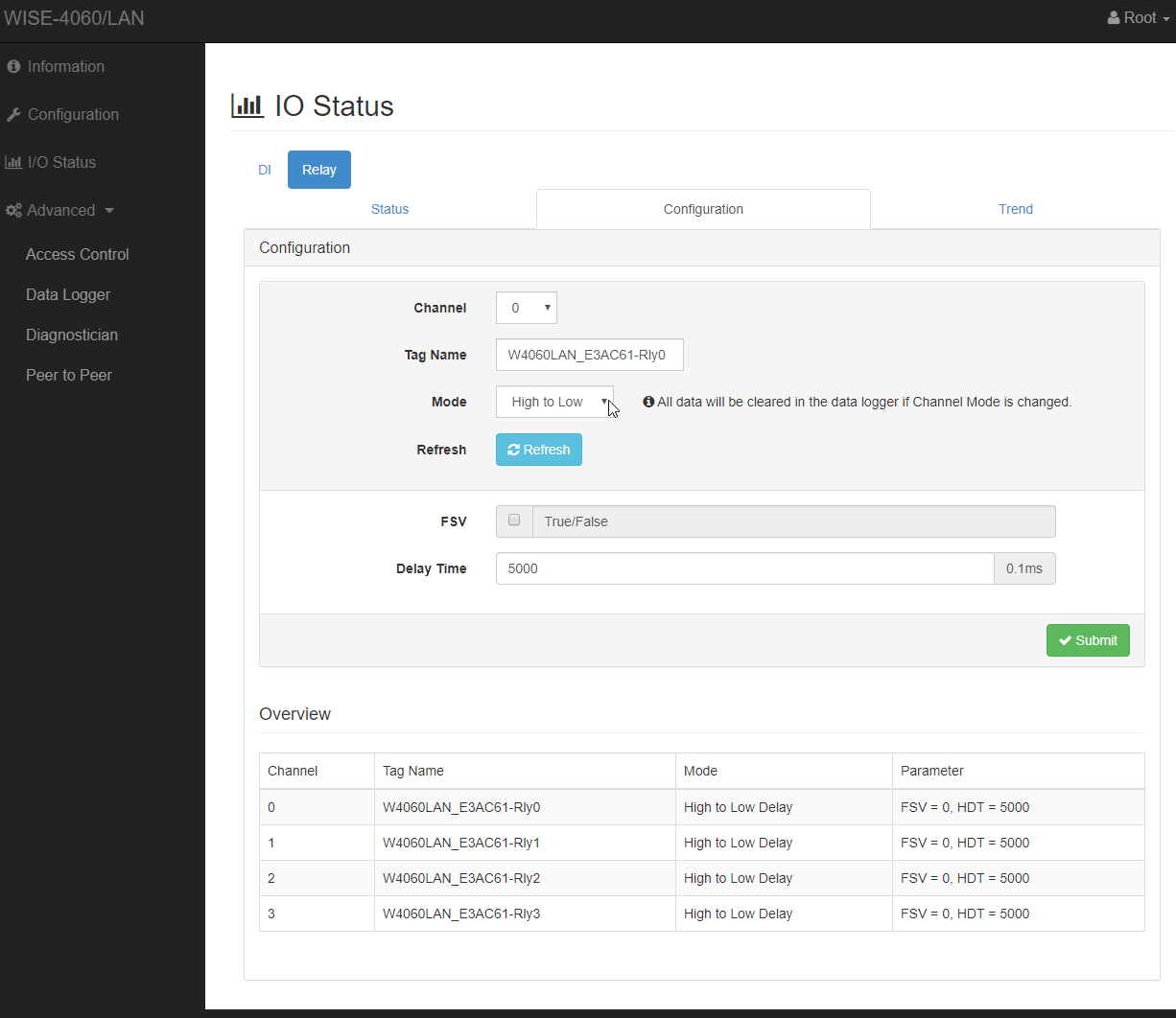
Channel Configuration
Choose the Channel from the dropdown. The Channel needs to match the one from the mapping in the .env.rc file in the SmartFace setup. For each channel then you have 3 modes to choose from. Their usage depends on your use case and you setup, especially on the setup of the device that the network relay is connected to.
- Pulse Output
This option sends only one value at once. Useful when the final device does not expect closing signal, only the opening

- High to Low
Sends two values at once, with a delay. Useful for opening doors when the high pulse opens the doors. After a set delay the value changes to low, so the doors are closed again.

- Low to High
Sends two values at once, with a delay. Useful for opening doors when the low pulse opens the doors. After a set delay the value changes to high, so the doors are closed again.